HX
Direct-contact heat exchange
Hot flue gas is bubbled directly through liquid, avoiding the thermal resistance of a solid heat exchanger wall.
BubblePipe converts conventional stacks into condensing scrubber assets: hot flue gas is bubbled through liquid, heat is recovered, and pollutants are captured before release.
A bubble pipe system routes exhaust through a liquid column, creating large gas-liquid contact area for direct-contact heat exchange, condensation, impaction, diffusion, and chemical absorption.
Hot flue gas is bubbled directly through liquid, avoiding the thermal resistance of a solid heat exchanger wall.
Cooling below the 45-65°C dew point captures latent heat, adding roughly 2.26 GJ per ton of condensed water.
Particles and gases are removed by impaction, diffusion, and chemical absorption into the scrubbing liquid.
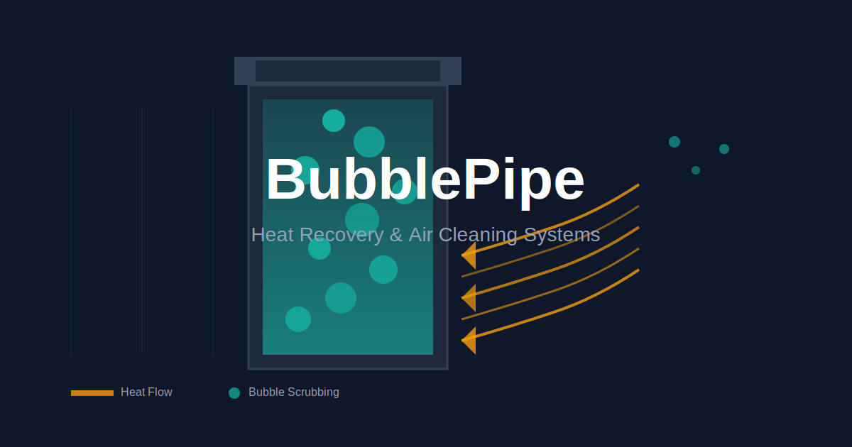
Primary gas-liquid contacting vessel.
Creates uniform small bubbles.
Transfers heat to useful sinks.
Prevents liquid carryover.
Controls pH, chemistry and flow.
Monitors pressure, temperature and bypass.
From furnace to useful heat: follow the flue gas through the bubble column to thermal recovery and cleaner exhaust.
Direct gas-liquid contact captures both sensible heat from cooling and latent heat from condensation, including energy usually lost up the chimney.
Overall efficiency gain when latent heat is captured.
Waste heat recovery rate depending on return-water temperature.
Fuel energy otherwise lost in flue gas.
Latent heat yield per ton of condensed water.
Thermal energy is captured as flue gas cools from inlet temperature toward the liquid or outlet target.
40-60% contributionWater vapor releases additional thermal energy when cooled below its dew point, a key advantage of condensing systems.
40-60% contributionImpaction, diffusion and chemical absorption remove particulates, acid gases and metals in a single wet stage.
Typical parameters for custom-engineered systems across foundries, steel plants, biomass facilities, cement, glass and chemical process industries.
| Parameter | Range | Design note |
|---|---|---|
| Gas flow capacity | 170-297,000 m3/h | Modular columns in parallel. |
| Inlet gas temperature | 150-800°C | Pre-cooling required above 400°C. |
| Outlet gas temperature | 40-60°C | Below dew point for latent heat recovery. |
| Liquid-to-gas ratio | 0.5-3.0 L/m3 | Higher ratios improve removal efficiency. |
| Pressure drop | 500-2,500 Pa | Compensated by induced draft fan. |
| Liquid column depth | 1-5 m | Greater depth increases contact time. |
| Residence time | 1-5 s | Minimum contact for absorption. |
| Energy consumption | <1-3% of output | Offset by recovered heat. |
Operational availability.
System lifetime.
Maintenance rhythm.
Materials selected by exhaust chemistry and temperature.
CAPEX, operating costs and ROI depend on scale, fuel displacement, recovered heat use and emission-control requirements.
Simple payback, typically 24-36 months.
Internal rate of return for heat-integrated systems.
Annual avoided-fuel savings from heat recovery.
Net present value over a 20-year operating life.
From foundries to steel plants and biomass power: real-world patterns for heat recovery and air cleaning.
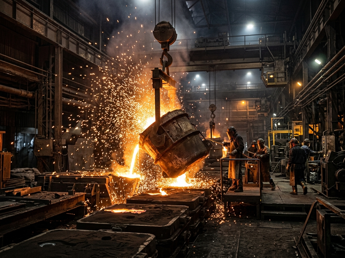
Combined wet scrubbing and regenerative thermal oxidation reduced hazardous air pollutants while recovered heat preheated process air.
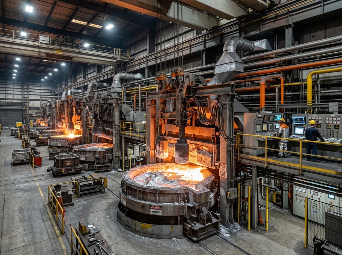
Condensing scrubber and heat exchangers captured exhaust heat from 400-700°C furnace streams.

Wet flue gas cleaning recovered latent and sensible heat for a district-heating return line.
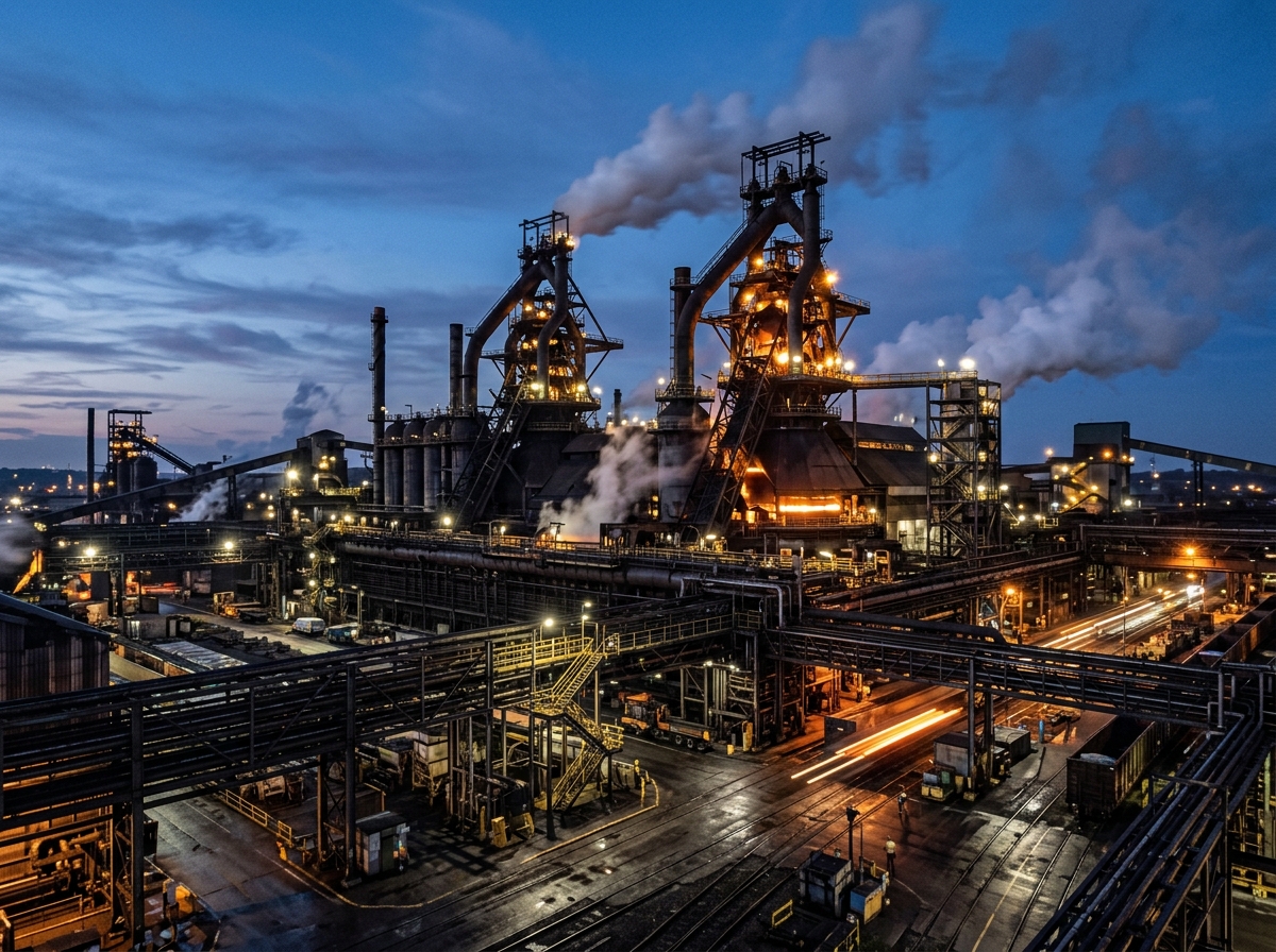
Multi-stage cooling, waste heat boiler, evaporative cooling and condensing scrubber reduced energy waste.
BubblePipe provides direct pollutant reduction and indirect CO2 savings from avoided fuel, while supporting major regulatory frameworks.
Typical avoided emissions per installation by displacing fossil-fuel heat. A 2 MW thermal system operating 6,000 h/year can avoid roughly 2,400 tonnes CO2/year when replacing natural gas heat.
Supports Best Available Techniques requirements.
Reduces carbon footprint and trading obligations.
Targets hazardous air pollutant standards.
Aligns with multi-pollutant emission standards.
An activated carbon bed in the scrubbing-water circuit captures residual metals and gases, turning stack waste into recoverable resources.
High-surface-area carbon adsorbs vapor-phase mercury, dioxins/furans, residual VOCs, odours and heavy-metal traces that a water scrubber alone cannot fully capture.
0.5-50+ MW sensible and latent heat for heating loops.
0.1-2 t/h treated and reused to reduce freshwater demand.
Hg, Pb, Zn and Cd streams sent to specialized refiners.
Fe, Zn and Al oxides can return to smelting feed.
SO2 plus lime yields marketable CaSO4.
Spent carbon is thermally regenerated or valorized.
Bubble pipe technology is modular: it scales from a small foundry workshop to a large integrated steel complex.
<5,000 m3/h flue gas, 0.5-2 MW recovered, $270k-$540k CAPEX.
5,000-50,000 m3/h flue gas, 2-15 MW recovered, $540k-$1.6M CAPEX.
>50,000 m3/h flue gas, 15-50+ MW recovered, $1.6M-$2.7M+ CAPEX.