Wankel Rotary Engine Hybrid System
A comprehensive technical reference for integrating PEM hydrogen electrolysis with Wankel rotary engines. Gasoline priority with on-demand H₂/O₂ enrichment for improved combustion efficiency and dramatically reduced emissions. Featuring coaxial counter-rotating copper wheel alternators (outer and inner wheels on the same axis, spinning in opposite directions) driven from the Wankel bottom output shaft, plus a gas compression-expansion water recovery system that condenses exhaust moisture to feed the electrolyzer.
System Architecture
Power flow through the Wankel H₂ hybrid drivetrain.
How It Works
The mechanical hybrid architecture prioritizes gasoline while using surplus power for hydrogen production.
Gasoline Primary
The Wankel engine runs on gasoline as primary fuel. The bottom output shaft drives a coaxial counter-rotating copper wheel alternator — two concentric rings spinning in opposite directions on the same axis.
Water → H₂ + O₂
The PEM electrolyzer splits water into hydrogen and oxygen. Water is supplied by the gas compression-expansion recovery system that condenses moisture from exhaust, supplemented by an onboard tank.
Enhanced Combustion
Hydrogen and oxygen are injected back into the engine, improving flame speed, enabling leaner combustion, and reducing CO, HC, and CO₂ emissions significantly.
Single Engine Car Configuration
A compact hybrid architecture featuring one Wankel rotary engine. The bottom output shaft drives both the differential (for the wheels) and a coaxial counter-rotating copper wheel alternator — two concentric copper rings on the same axis spinning in opposite directions — that generates DC power for the PEM electrolyzer. Exhaust gases pass through a compression-expansion condenser that recovers water to feed back into the electrolyzer.
System Specifications
Power Distribution
- • Bottom output shaft connects to transmission
- • Standard differential distributes torque to wheels
- • Direct mechanical coupling — no energy conversion losses
- • Brake thermal efficiency improved with H₂ enrichment
- • Coaxial copper wheels (same axis, opposite spin) generate AC → rectified to DC
- • DC bus distributes to electrolyzer + auxiliaries
- • PEM electrolyzer splits H₂O at ~55 kWh/kg efficiency
- • ECU-controlled H₂/O₂ injection back into engine intake
Gas Mixture System
Water Recovery: Gas Compression-Expansion
Instead of relying solely on an external water tank, the system recovers water from engine exhaust using a gas compression-expansion condenser. Combustion of gasoline and hydrogen produces significant water vapor (H₂O) in the exhaust stream.
How It Works
- → Exhaust gas exits the Wankel engine at 400–700°C containing H₂O vapor
- → A compressor stage raises gas pressure, increasing the dew point
- → The gas is cooled through an expansion stage and heat exchanger
- → Water condenses out and is collected, filtered, and deionized
- → Recovered water is fed directly to the electrolyzer bank
Recovery Rates
PEM Electrolyzer Detail
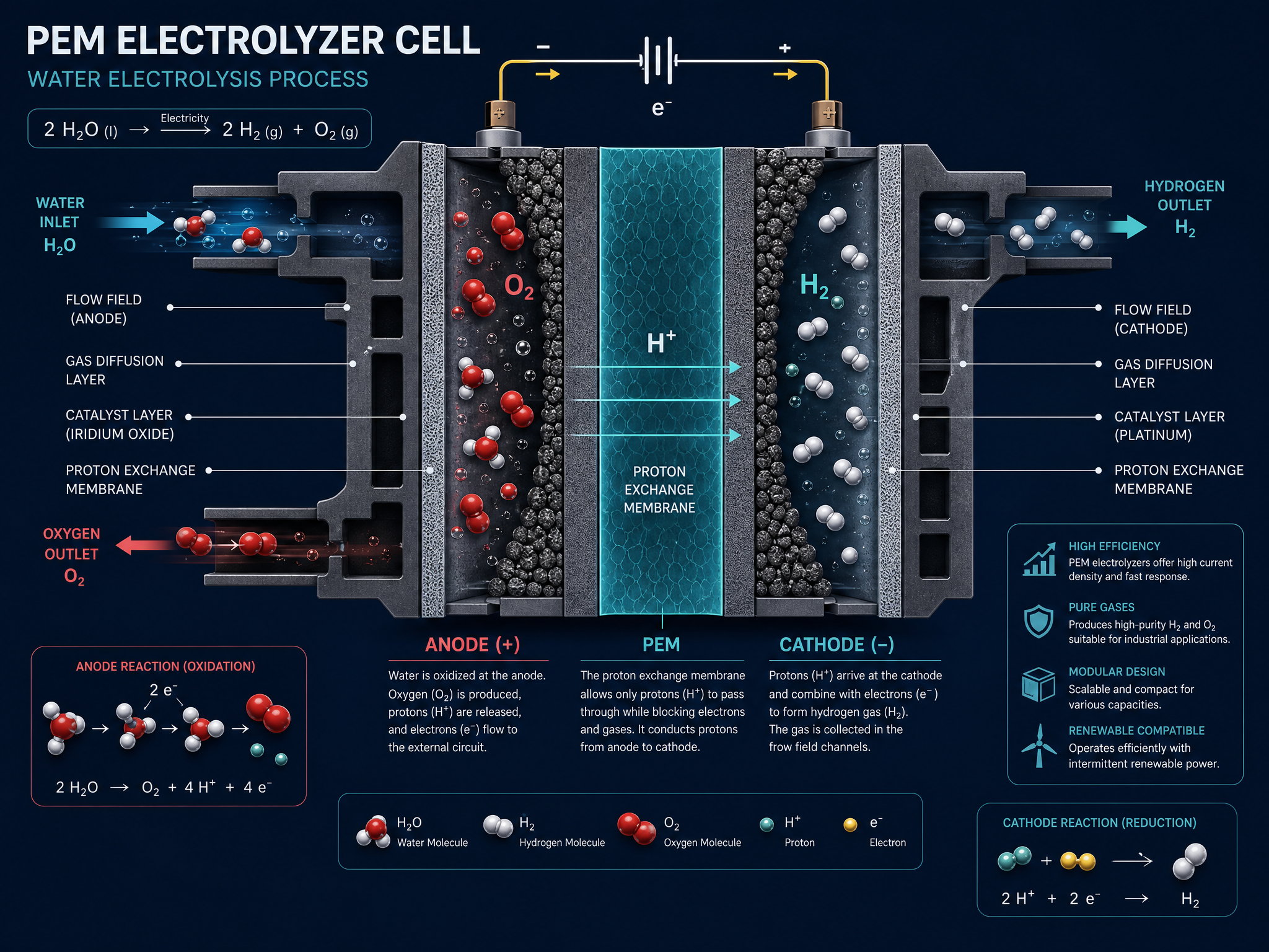
The PEM electrolyzer is the heart of the hydrogen generation subsystem. It uses DC electricity from the coaxial alternator to split water — both recovered from exhaust and from the onboard tank — into hydrogen and oxygen.
Dual Engine Bus Configuration
Two counter-rotating Wankel engines, each with its own coaxial counter-rotating copper wheel alternator (concentric rings on the same axis). Both alternators feed a shared DC bus powering a high-capacity PEM electrolyzer bank. A shared gas compression-expansion water recovery unit collects exhaust condensate from both engines.
System Specifications
Why Coaxial Counter-Rotating Wheels?
Same-Stage Design
Both copper wheels share the same axis — outer ring CW, inner ring CCW. Compact coaxial packaging saves space and weight vs. side-by-side layouts.
Vibration Cancellation
Concentric counter-rotation on a single axis perfectly cancels gyroscopic torque and reduces drivetrain vibration for passenger comfort.
Doubled Relative Speed
The relative angular velocity between the inner and outer rings is effectively doubled, generating more electrical output from the same shaft RPM.
Car vs. Bus Comparison
| Parameter | Car (Single) | Bus (Dual) |
|---|---|---|
| Engines | 1× 13B (1,308 cc) | 2× 13B (2,616 cc total) |
| Peak Power | ~180 HP | ~360 HP |
| Alternators | 1× coaxial CR pair | 2× coaxial CR pairs |
| Electrolyzer Power | 10–15 kW | 24–30 kW |
| H₂ Production | 0.18–0.27 kg/h | 0.44–0.55 kg/h |
| Water Consumption | 1.6–2.4 kg/h | 4.0–5.0 kg/h |
| Water Recovery | 0.5–1.0 kg/h | 1.5–3.0 kg/h |
| Torque Balance | Single coaxial CR | Dual coaxial CR + engine CR |
| Target Application | Sedan / Compact | Transit Bus / Heavy Duty |
Engineering Calculations
Power output formulas, electrolyzer sizing, hydrogen production rates, and combustion efficiency analysis.
Engine Power Output
P = power (W), N = speed (rpm), T = torque (N·m)
For a 13B engine at 6,500 RPM with 190 N·m torque:
Shaft Power Distribution
η_drive = driveline eff., η_alt = alternator eff.
With P_wheel = 80 kW, η_drive = 0.93, P_elec = 10 kW, η_alt = 0.90:
Performance Comparison
Electrolyzer Sizing
ṁ_H₂ = kg/h, P_elec = kW, SEC = kWh/kg
Faraday's Law
F = 96,485 C/mol, M_H₂ = 2.016 g/mol
Engineering constant: 1 A·h ≈ 0.0376 g H₂
Key Constants
Interactive Calculator
H₂ Production vs. Power
| Power (kW) | H₂ (kg/h) | H₂ (Nm³/h) | O₂ (kg/h) |
|---|---|---|---|
| 5 | 0.091 | 1.01 | 0.727 |
| 10 | 0.182 | 2.02 | 1.455 |
| 15 | 0.273 | 3.03 | 2.182 |
| 20 | 0.364 | 4.04 | 2.909 |
| 25 | 0.455 | 5.05 | 3.636 |
| 30 | 0.545 | 6.06 | 4.364 |
| 50 | 0.909 | 10.09 | 7.273 |
Emission Reductions
Combustion Benefits
Why H₂ Improves Combustion
- → Flame speed ~8× faster than gasoline
- → Wide flammability limits (4–75% in air)
- → Extremely low ignition energy (~0.02 mJ)
- → Reduces cycle-to-cycle variation
Safety Systems
Multi-layered safety architecture covering leak detection, pressure management, thermal control, and NOx emission mitigation.
Hydrogen Properties
Hydrogen is colorless, odorless, and highly flammable with near-invisible flames. Its extremely low ignition energy and wide flammability range demand rigorous engineering controls.
Multi-Layer Safety Architecture
Leak Detection
Multiple hydrogen sensors at high points and enclosed cavities. Catalytic bead and electrochemical sensors provide redundant detection with <1 second response time.
Automatic Shutoff
Fail-safe solenoid valves on all hydrogen lines. Triggered by leak detection, crash sensors, overpressure, or ECU fault. Spring-loaded to close on power loss.
Pressure Management
Thermally-activated pressure relief devices (TPRDs) on buffer tanks. Burst discs sized for worst-case thermal runaway. Operating pressure: 1–2 bar above intake manifold.
Ventilation
Forced-air ventilation in all enclosed compartments. Vent routing directs any released H₂ upward and away from occupants. ATEX-rated fans and ducting.
Temperature Control
Dual-loop liquid cooling for electrolyzer (60–80°C) and engine. Temperature sensors on all H₂ lines, buffer tanks, and electrolyzer stack. Auto-shutdown above 95°C.
Continuous Diagnostics
Real-time monitoring during operation, parking, and shutdown. Fault codes for sensor degradation, seal wear, and performance drift. OBD-II compatible reporting.
NOx Emission Mitigation
Materials & Standards
- • H₂-embrittlement-resistant alloys for all wetted components
- • Oxygen-clean stainless steel (316L) for O₂ lines
- • PTFE or FKM seals rated for H₂ service
- • Flame arrestors at all tank outlets
- • Tank proof/burst testing per applicable standards
- • Crash integrity testing for all gas storage
- • ATEX-rated electrical components in gas zones
- • Purge procedures documented for maintenance
Control Logic
The ECU manages fuel, hydrogen, and oxygen injection ratios in real-time, coordinating with the electrolyzer power control and emissions feedback.
Fuel / H₂ / O₂ Ratio Management
Port injection timed to intake port opening. Pulse width controlled by MAP, RPM, and lambda feedback.
Timed injection into intake manifold during intake stroke. Starts 30–60° before intake port opens for thorough mixing.
Continuous low-rate upstream of throttle body. Rate-limited by real-time NOx sensor. Max 4% of intake mass flow.
H₂ first → Gasoline second → O₂ blended last. Maximizes flame speed benefit.
Power Distribution Logic
⚡ Alternator Load Control
⚠ Safety Interlocks
Bus-Specific Control Logic
The bus ECU manages both engines as a synchronized pair. Counter-rotation maintained by independent speed control with torque-matching to within 2%.
If one engine must be shut down, the ECU smoothly transitions to single-engine mode with appropriate alternator load reduction.
Both engines draw from a shared H₂ buffer tank via individual injectors. The ECU balances injection quantities based on each engine's MAP and RPM feedback.
The larger electrolyzer bank (24–30 kW) can be segmented: if one alternator fails, the other powers a reduced section maintaining H₂ supply at a reduced rate.